Linn Komri Service Information
The Linn Komri was introduced in 2001 and discontinued in 2010.
The speakers are no longer serviced or supported by Linn.
Information on this page is provided to document the components in the Komri for those attempting service/repair.
Please get in contact if you require service on your Komri loudspeakers.
Disclaimer: This page describes procedures involving mains voltage and potentially hazardous electronic components. These repairs should only be performed by qualified personnel with appropriate knowledge, tools, and safety precautions. Incorrect handling can result in serious injury, electric shock, fire, or equipment damage. Proceed entirely at your own risk.
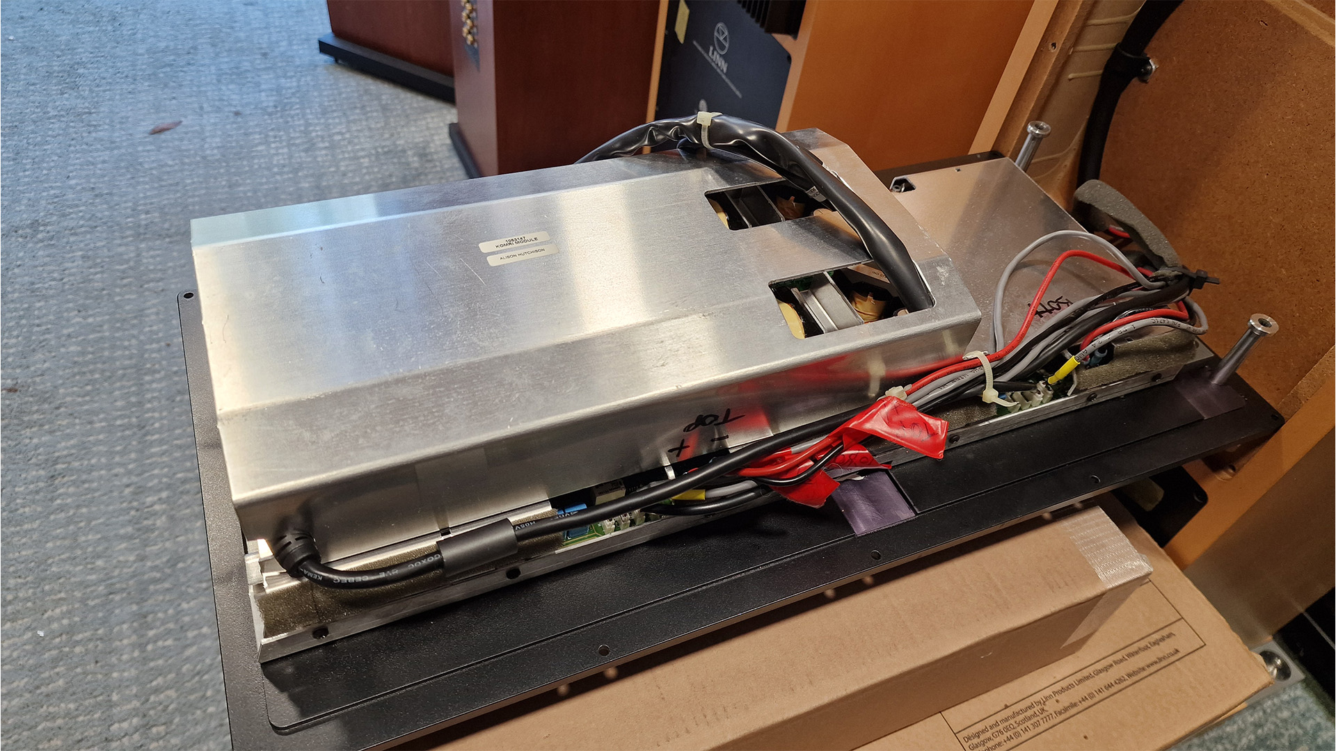
LINN Komri Exploded view
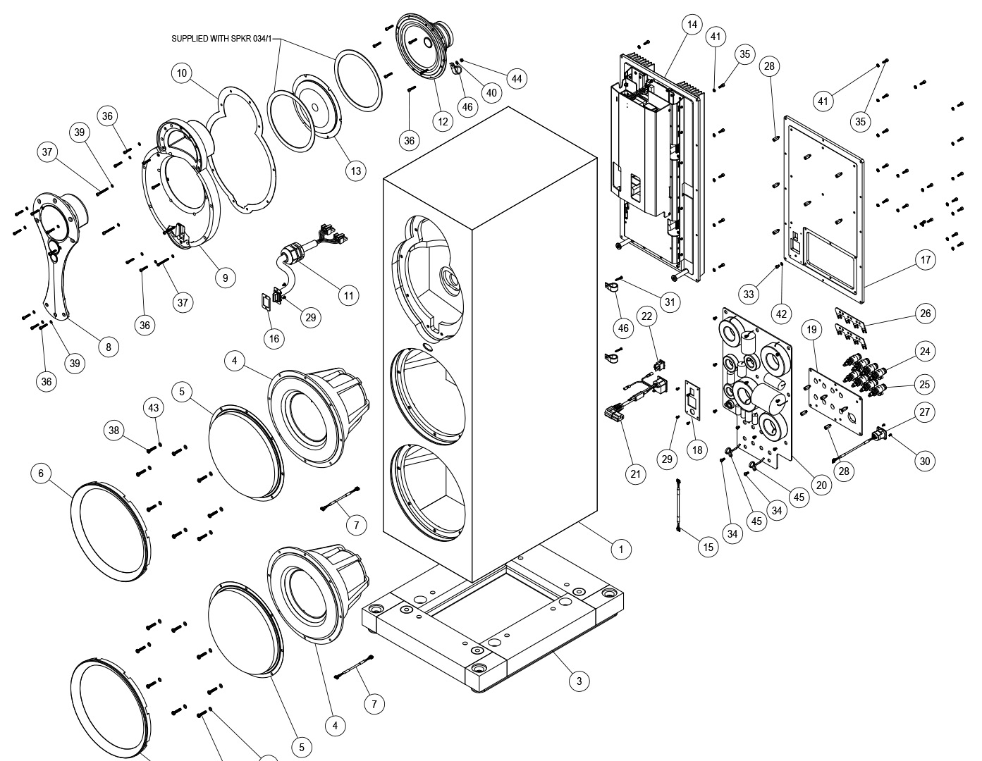
Drive Units
- 4K Array
- 3" Mid Range drive SPKR 035/1
- 1" treble unit SPKR 036/1
- Super Tweeter SPKR 037/1
- 6inch Upper bass driver SPKR 034/1
- 10inch Bass driver SPKR 033/3 - measured 6.9ohm across terminals
- 10inch Bass driver SPKR 033/3 - measures 7.1ohm across terminals.
Passive Crossover
tbc
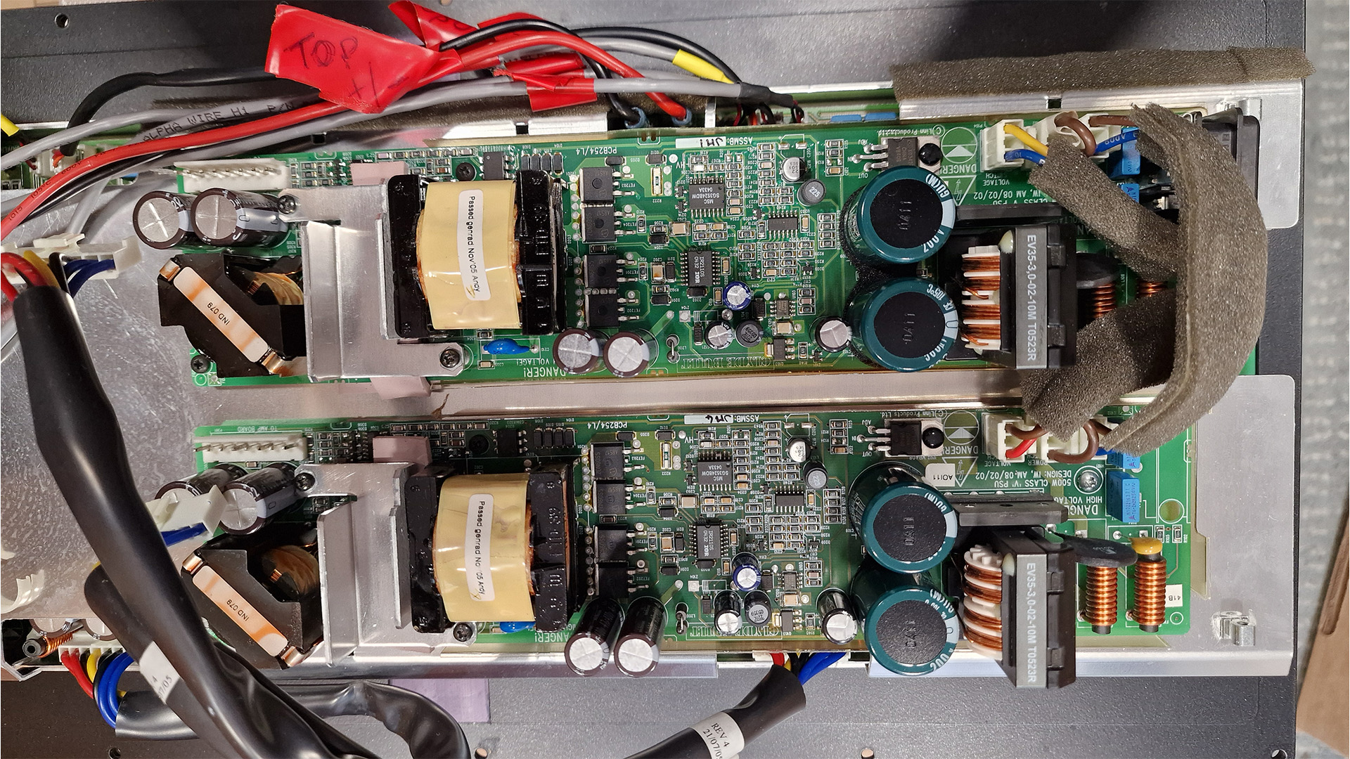
Power Supplies
2 x PCAS254 (Non-Dynamik) - Could be replaced by Dynamik PSU PCAS754 (with power input modified connections)
These are the same power supplies found in Chakra Amps (Akurate 2200, Majik DSM etc) of this period with modified mains input on one of the boards.
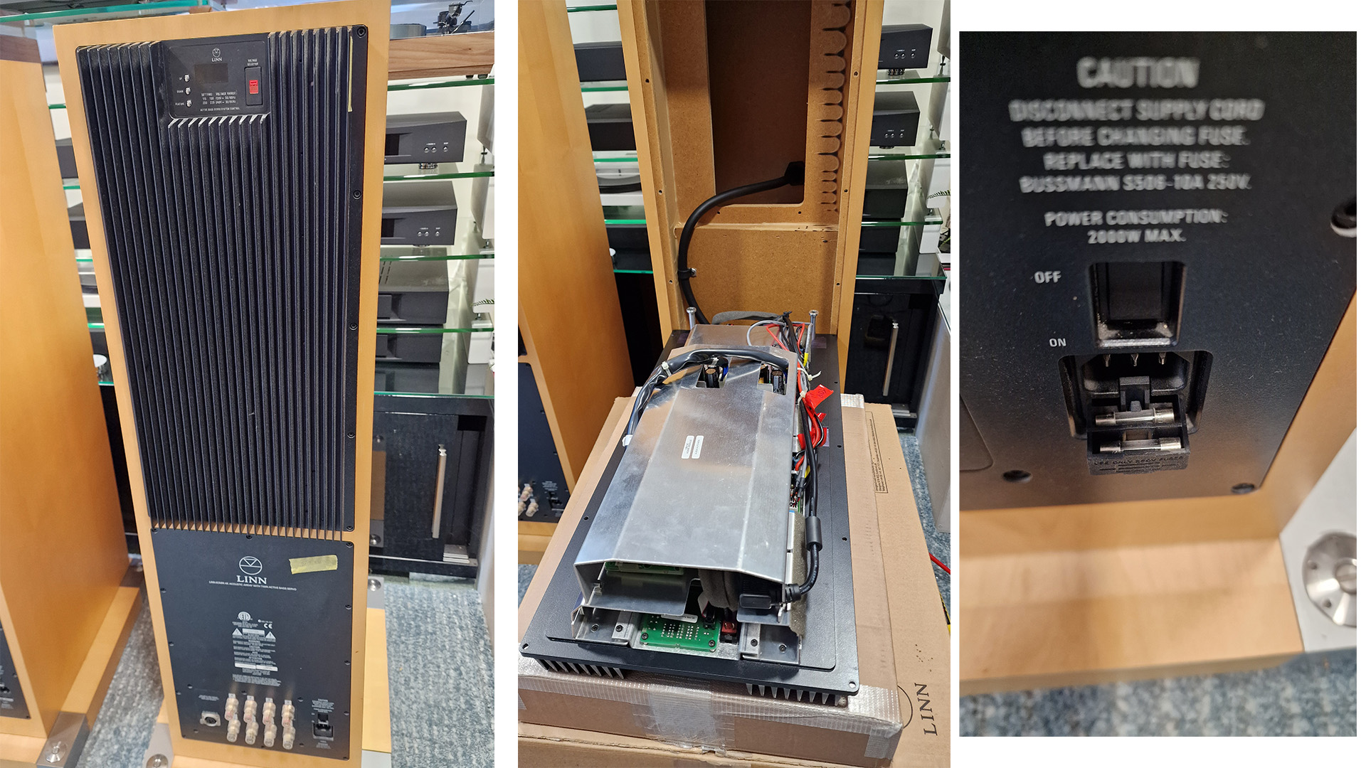
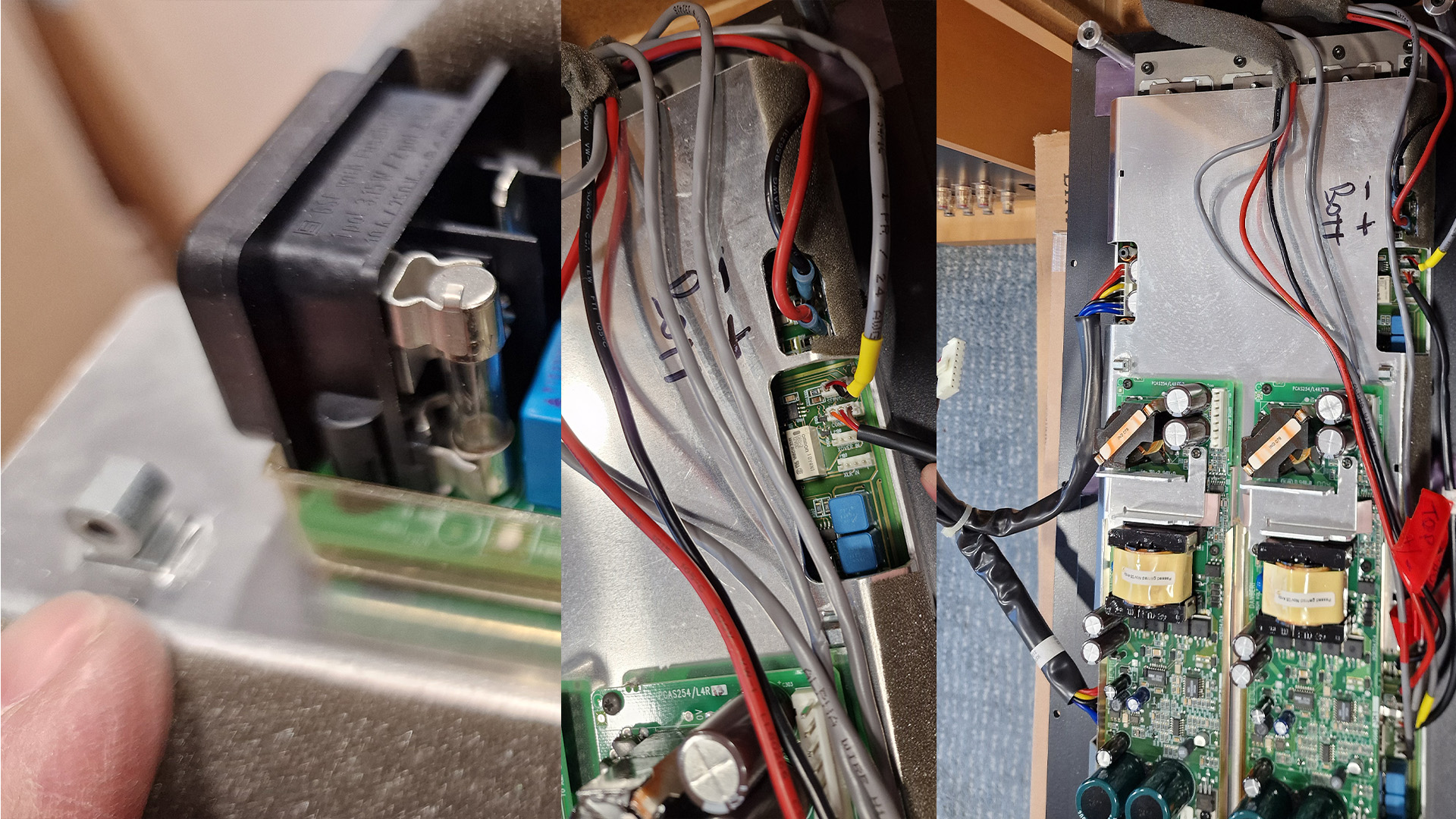
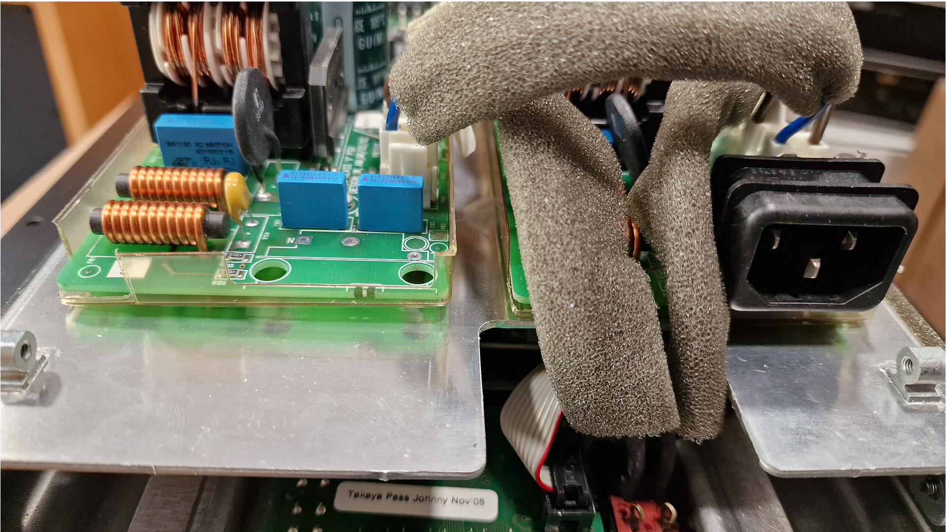
Fuses
There is a fuse in the IEC mains input on the rear of the speaker (with a spare).
There is also a fuse on the input power supply PCAS254 behind the internal IEC.
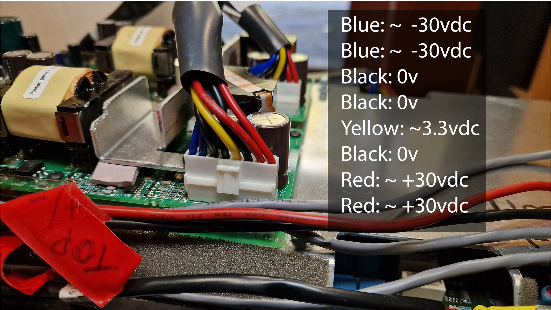
Linn PCAS254 Power Supply outputs
| Blue | -30v |
| Blue | -30v |
| Black | 0v |
| Black | 0v |
| Yellow | 3.3v |
| Black | 0v |
| Red | +30v |
| Red | +30v |
Amplifier Boards
The Komri has two actively driven bass speakers. The main amplifier boards are held on a large heatsink on the rear of the speaker.
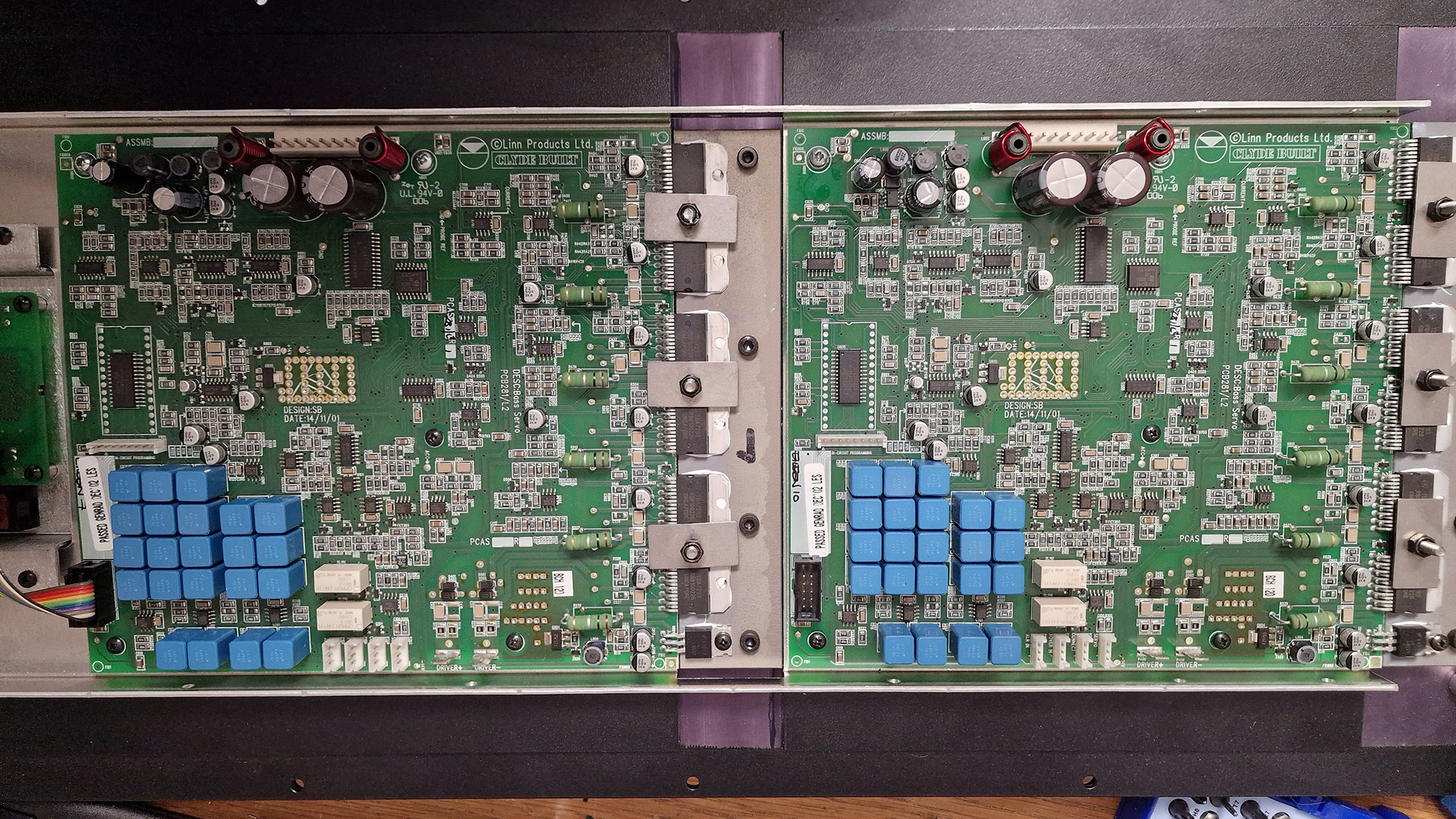
The three boards are:
LED display board:
Upper bass amplifier: PCAS281
Lower bass amplifier: PCAS281
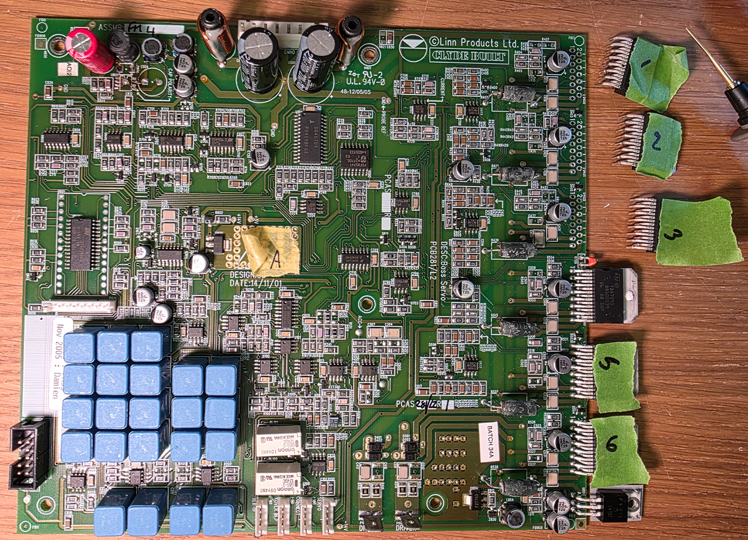
Amplifier Board Components (PCAS281)
Here is a summary of the main componets on a Komri amplifier board.
Drivers TDA7293 - "TDA7293 high-power DMOS audio amplifier IC made by STMicroelectronics — the heart of a 100 W class-AB audio amplifier channel"
6 x TDA7293 (Multiwatt15H)
1 x LM337 - negative adjustable voltage regulator (–1.25 V to –37 V)
Electrolytic Capacitors
Probably one of the first things to test and change given the age.
2 x 220uF 100v Radial 16mm diameter x 26mm height
1 x 120uF 50v Radial 8mm diameter x 15mm height
1 x 100uF 63v Radial 10mm diameter x 14mm height
16 x SMD caps 22uF 50v (2250s2k8) Mouser Part Number: 667-eee-1ha220wp
1 x SMD cap 2.2uF 50v
Polypropylene Film Capacitors
Blue cube like
22 x 150nF 5%
SMD Capacitors
tbc
SMD IC Packages
| Board Marking | Part No | Notes |
| U001 | ST62T65C6 |
8-bit microcontroller Likely system control and protection tasks:
|
| U200 | PCF8574T | I²C I/O Expander |
| U205 | DG407DY | Analog Switch / Multiplexer IC |
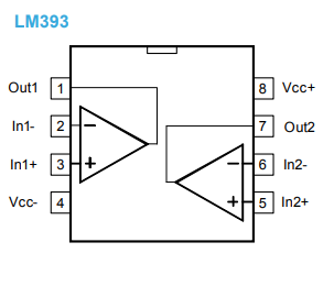
| U304 / U701/ U702 | 91P233 | dual operational amplifier |
| U800 | LM2594 |
Marked "3137 2594H M-ADJ" “2594” → National/TI LM2594 Simple Switcher buck regulator (150 kHz) “M-ADJ” → SOIC-8 (“M”) adjustable output version step-down (buck) switching regulator that converts the high DC rail (e.g., +30–50 V) to a lower rail for logic/controls (e.g., +5 V or +12 V). Mouser Part: 926-LM2594HVMADJNOPB |
| D800 | ES2D |
"FA502 High-speed Schottky rectifier: Part identification ES2D 2 A average forward current 200 V reverse voltage Fast / Schottky recovery SMD SMA/DO-214AC package Used as the freewheel/catch diode in the LM2594 buck regulator stage.
Mouser Part No 603-ES2D |
Another go at ICs
| Designation | Part Markings | Part | Notes |
| U001 | ST62T65C6 | ST62T65C6 | 8-bit microcontroller |
| U100 | 88 OPA 2604AU 512EE | OPA2604AU |
High-performance dual audio operational amplifier
|
| U101 | 88 OPA 2604AU 512EE | OPA2604AU |
High-performance dual audio operational amplifier
|
| U103 | 88 OPA 2604AU 512EE | OPA2604AU |
High-performance dual audio operational amplifier
|
| U104 | 393 9520 | LM393D |
dual voltage comparator
|
| U200 | PCF85741 A27700 G05133 | PCF8574T |
I²C I/O Expander
|
| U201 | 88 OPA 2604AU 512EE | OPA2604AU |
High-performance dual audio operational amplifier
|
| U202 | 88 OPA 2604AU 512EE | OPA2604AU |
High-performance dual audio operational amplifier
|
| U203 | 88 OPA 2604AU 512EE | OPA2604AU |
High-performance dual audio operational amplifier
|
| U205 | DG407DY P0419BFG3 | DG407DY |
Analog Switch / Multiplexer IC
|
| U206 | DG411DY G0425AD | DG411DY |
Quad SPST Analog Switch
|
| U210 | 88 OPA 2604AU 512EE | OPA2604AU |
High-performance dual audio operational amplifier
|
| U300 | DG411DY G0425AD | DG411DY |
Quad SPST Analog Switch
|
| U301 | 88 OPA 2604AU 512EE | OPA2604AU |
High-performance dual audio operational amplifier
|
| U303 | 88 OPA 2604AU 512EE | OPA2604AU |
High-performance dual audio operational amplifier
|
| U304 | 914I 976450 | 91P233 |
dual operational amplifier
|
| U305 | TL032C 54M C8ET | TLVX TL032C |
Low-power dual operational amplifier
|
| U403 | TL032C 54M C8ET | TLVX TL032C |
Low-power dual operational amplifier
|
| U404 | TL032C 54M C8ET | TLVX TL032C |
Low-power dual operational amplifier
|
| U405 | TL032C 54M C8ET | TLVX TL032C |
Low-power dual operational amplifier
|
| U503 | TL032C 54M C8ET | TLVX TL032C |
Low-power dual operational amplifier
|
| U602 | 339 Z39437 | LM339D |
STMicroelectronics LM339D — a quad comparator in SOIC-14.
|
| U604 | 393 E9520 | LM393D |
dual voltage comparator
|
| U605 | 393 E9520 | LM393D |
dual voltage comparator
|
| U701 | 914I 976450 | 91P233 |
dual operational amplifier
|
| U702 | 914I 976450 | 91P233 |
dual operational amplifier
|
| U707 | 88 OPA 2604AU 512EE | OPA2604AU |
High-performance dual audio operational amplifier
|
| U800 | 2594H M-ADJ | LM2594 |
step-down switching regulator (buck regulator
|
Relays
White rectangular boxes
2 x OMRON 2961Y1 G6S-2 12 VDC - signal-level DPDT relay
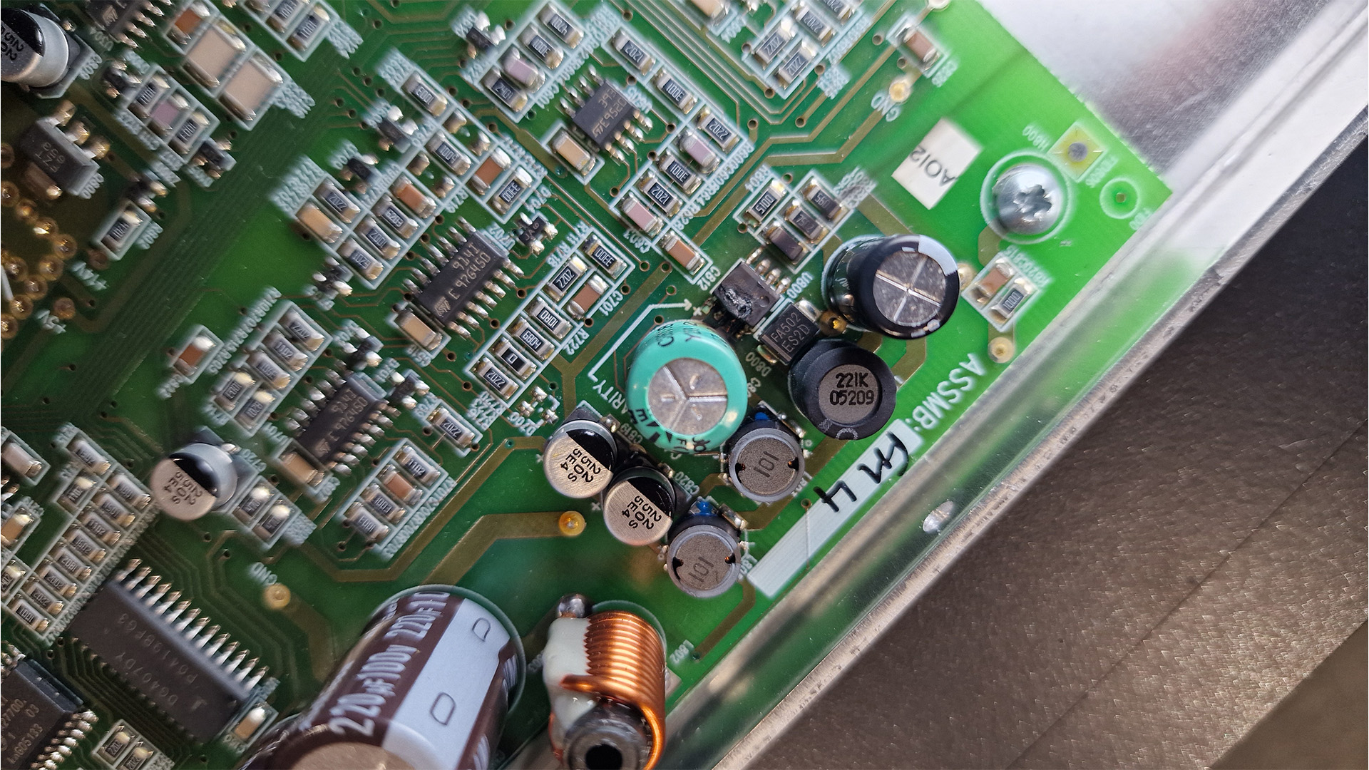
FAULT FINDING
First Clues
On the customer Komri a visual inspections shows the regulator U800 / LM2594 burnt out - the next steps are to test all the components around this for a short on the 12v/5v rail. Place your bets on the capacitors.
Quick ESR check shows:
C800 -120uF 50v electrolytic - ok
C804 - 100uF 63v electrolytic - leaky
C820 - 22uF 50v smd - leaky
C819 - 22uF 50v smd - leaky
C113 2.2uF smd esr > 40ohm
C114 22uF 50v leaky
C131 22uF 50v - ESR 13.9ohm
C816 22uF 50v smd - measures cap 27uF/ESR 0.11
Next steps
- Remove components near burnt out LM2594.
- Test values out of circuit
- Test for shorts
- Replace LM2594 + resistors + smd caps
- Replace all caps.
Removed Suspect Capacitors around the LM2594 - main culprit is C804 - 100uF 63v electrolytic which tests as ESR > 40ohm, the SMD caps are all only just in spec.
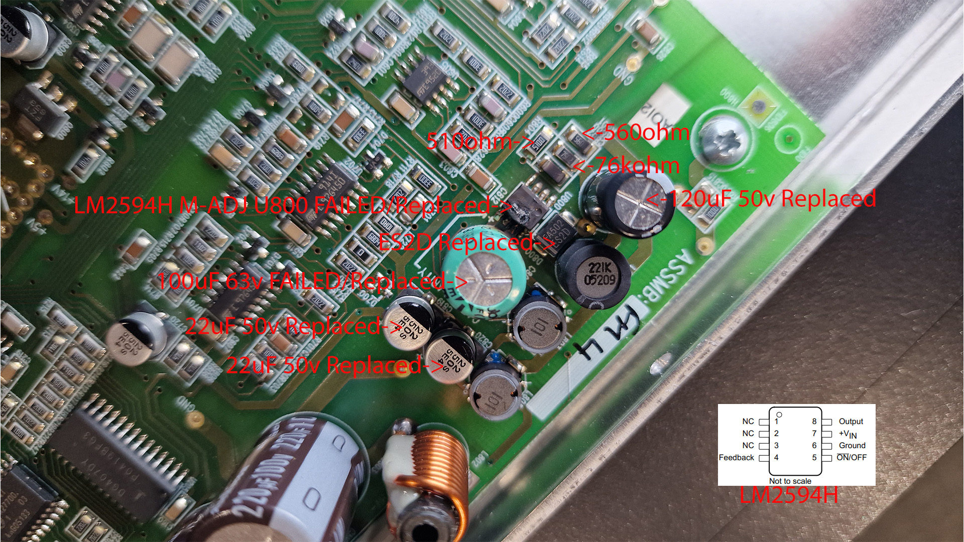
These componentrs are responsible for generating the +14v and the +5 supply to the board.
The -14v supply is good.
Having replaced the failed components there is still a short somewhere on the board.
Time to re-test surface mount components (caps, Diodes etc).
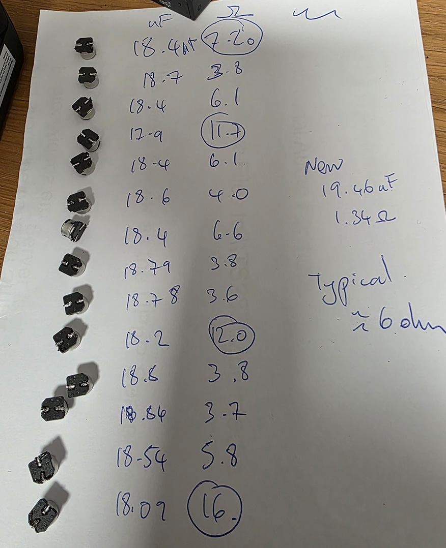
Out of specification Capacitors
Next we have the small 22uF 50v caps measured after removal. The new replacements typically read 19uF, 1.34ohm.
The main amps (TDA7293) and the negative regulator (LM337) need to be checked next - remove the TDA7293 and test out of circuit.
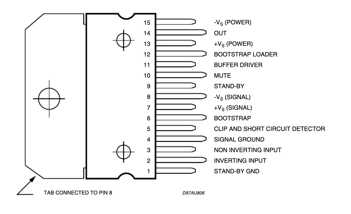
TDA7293 Pinout (Multiwatt15 Package)
| Pin | Name | Function |
|---|---|---|
| 1 | ST-BY GND | Stand-by ground reference |
| 2 | IN– | Inverting input |
| 3 | IN+ | Non-inverting input |
| 4 | SIGNAL GND | Small-signal ground |
| 5 | CLIP / SHORT DETECTOR | Output status pin |
| 6 | BOOTSTRAP | Bootstrap capacitor |
| 7 | +Vs (SIGNAL) | Positive supply for input/driver stage |
| 8 | –Vs (SIGNAL) | Negative supply for input/driver stage (TAB is also connected to this) |
| 9 | ST-BY | Stand-By control |
| 10 | MUTE | Mute control |
| 11 | BUFFER DRIVER | For modular/parallel operation |
| 12 | BOOTSTRAP LOADER | Auxiliary bootstrap |
| 13 | +Vs (POWER)** | Main + supply for power stage |
| 14 | OUT | Power output |
| 15 | –Vs (POWER)** | Main – supply for power stage |
For each of the 6 TDA7293,do these three measurements in ohms:
Pin 14 → Pin 4 (OUT → GND)
Pin 14 → Pin 13 (OUT → +Vs POWER)
Pin 14 → Pin 15 (OUT → –Vs POWER)
This reveals 1,2,3 are all suspect. Removed.
Out of circuit, measure:
Pin 14 (OUT) → pin 13 (+Vs POWER)
Pin 14 (OUT) → pin 15 (–Vs POWER)
Pin 13 → pin 15
Anything that measures just a few ohms in any of those is definitely dead.
Checking +30 -> GND and -30 -> GND now no longer shorted.
Replace 6 x TDA7293 and retest.
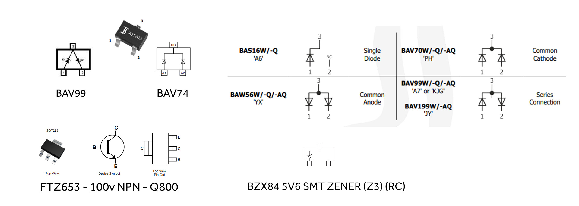
Diode Checks
There are a number of SMD diodes in the vacinity of the TDA7293H that need to be checked (actually test all the diodes on the whole board):
D400, D406 (8?), D407, D505, D507, D508 - these are marked 'A7' and are BAV99 high-speed switching diode pair in SOT-23 package.
Test:
- Red probe on the middle pin (3), black probe on pin 1 → you should see a forward drop ~0.6–0.8 V.
- Red probe on pin 2, black on pin 2 → again ~0.6–0.8 V.
- In all reverse directions, the meter should show open circuit.
Dxxx marked 'A1' - BAW56 dual high-speed switching diode (two diodes in series in one package).
Here is are the readings for the diodes (SOT-23 packages):
Meter in doide mode. R = Red probe,1 = pin 1, 2 = pin 2, 3 = pin 3. e.g R3 ->1 red probe on pin 3, black on pin 1.
Z800 is faulty and needs to be replaced. This is responsible for the 5v supply. Depending on how this has failed could mean the components on the 5v supply are also damaged....
Some Progress..
Zener Diode (5v6) Z800 replaced. Board powered on from a bench supply. I now see +11v (should be ~ 14v), +5.3v, -14v supplies.
Here is a thermal image of the board powered from current limited bench supply (not sure I believe the temps indicated):
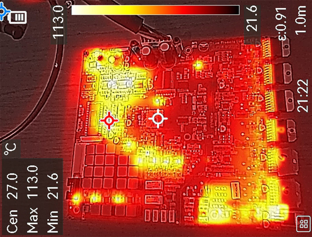
Still some digging to do...
I'd only replaced the 3 obviously faulty TDA7293 when I took the thermal image above. You can see the three on the lower right hand side are generating more heat in the image - so I replaced them and now my voltage rails are +13.9, +5, -14.01 so looking better.
I reconnected the amp board to the LED display board and this now powers up correctly and appears to work as expected.
In the top right area of the thermal image there are a couple of IC (U701, U702) - they seem to be hotter than expected so more investigation there.
It is a busy time of year for ripcaster (December 2025) - so I'm only spending the odd 15mins on this project as and when I can and progress is slow.
U701, U702 -> TS914ID - Operational Amplifiers - Op Amps Quad Rail-to-Rail 3V

Nearby (also 'warm') we have U606 (or U605 difficult to read) : LM393D
U602 LM339N or LM339M - TBC